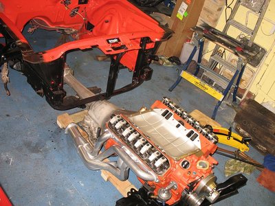
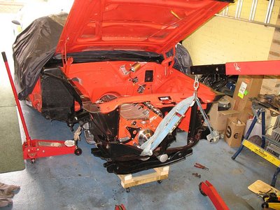
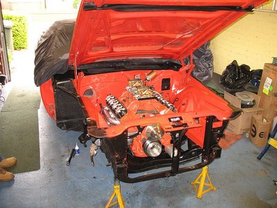
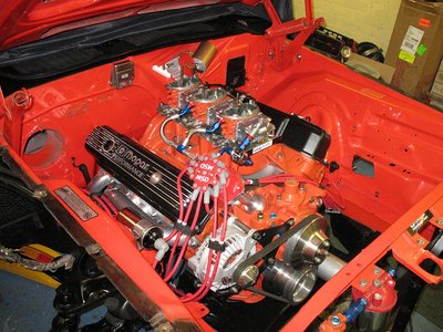
Dave, I'm really happy to see you are making progress, both on the car and with your illness. Comparing the effort it took to get the engine and trans out of my car with what it took to get it all back in, lifting the car was the way to go.
-

JackT - Frequent Poster
- Posts: 390
- Joined: 18 Oct 2003 2:29
- Location: West Hills, California, USA
Thanks guys. I will "get there" eventually. 
Both!
It is the biggest I thought I could fit. About twice the size of my old one.
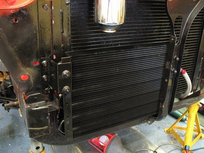
By the way. Never fit one so it is touching the radiator. Leave a gap of at least a quarter inch.
spitfire9137 wrote:Are you using that oil cooler for the trans or the engine?
Both!
It is the biggest I thought I could fit. About twice the size of my old one.
By the way. Never fit one so it is touching the radiator. Leave a gap of at least a quarter inch.
-

dave-r - Grumpy Old Man
- Posts: 9842
- Joined: 12 Oct 2003 21:45
- Location: North of the Tyne, England
- spitfire9137
- Frequent Poster
- Posts: 277
- Joined: 05 May 2004 1:28
- Location: MD, USA
-

dave-r - Grumpy Old Man
- Posts: 9842
- Joined: 12 Oct 2003 21:45
- Location: North of the Tyne, England
Did it cause them to suffer an increase in Temperature due to lack of conduction/convection? Or cause stress cracks in the aluminum,(vibratory stress failure)? Just curious Dave. Thanks.dave-r wrote:Thanks guys. I will "get there" eventually. spitfire9137 wrote:Are you using that oil cooler for the trans or the engine?
Both!
It is the biggest I thought I could fit. About twice the size of my old one.
By the way. Never fit one so it is touching the radiator. Leave a gap of at least a quarter inch.
-

Eddie - Frequent Poster
- Posts: 6212
- Joined: 16 Oct 2006 21:26
- Location: Terre Haute, Ind.
It is an airflow thing.
Unless the cooling fins lined up exactly between the radiator and the cooler (and that is not going to happen) the air will find it difficult to pass though both.
But a small gap allows the air to wind its way through much easier. A quarter inch at least is needed for this. More would be better.
Unless the cooling fins lined up exactly between the radiator and the cooler (and that is not going to happen) the air will find it difficult to pass though both.
But a small gap allows the air to wind its way through much easier. A quarter inch at least is needed for this. More would be better.
-

dave-r - Grumpy Old Man
- Posts: 9842
- Joined: 12 Oct 2003 21:45
- Location: North of the Tyne, England
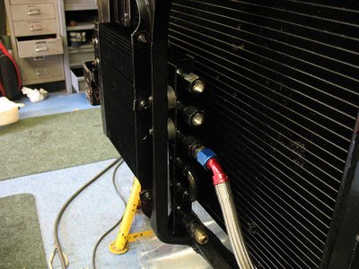
dave-r wrote:Yes. I run -8AN lines.
We talked about this awhile ago I think. All we could find was sandwhich adapters with 3/8 threads, is that what you are using? Do you think it will flow enough oil? I have been looking for one with 1/2 threads but have yet to find one.
- spitfire9137
- Frequent Poster
- Posts: 277
- Joined: 05 May 2004 1:28
- Location: MD, USA
spitfire9137 wrote:dave-r wrote:Yes. I run -8AN lines.
We talked about this awhile ago I think. All we could find was sandwhich adapters with 3/8 threads, is that what you are using? Do you think it will flow enough oil?
More than enough. The internal diameter of -8AN is only 1/16th more than 3/8.
You don't have to run every single drop of oil through the cooler for it to be effective. In fact you never can because a huge amount of oil is kept in the engine at any given time anyway. So it makes no difference at all.
It is like when you heat a pan of water. You only heat one part of it. The bottom. Yet it all reaches 100*C after a bit of time and stays that way.
Same when you are cooling something. But better because it is already cool before you start. So the cooler only has to maintain oil temp.
You will find that with a cooler the oil will easily keep to the same temp as the water. 180*F.
Don't forget that the water is cooling the block too!
-

dave-r - Grumpy Old Man
- Posts: 9842
- Joined: 12 Oct 2003 21:45
- Location: North of the Tyne, England
airfuelEddie wrote:I see, thanks Dave, hope you don't mind all the silly questions. soon my son will have me immersed in his Duster bracket car, and your's is going to be set up for the drags/dual purpose?
Yeah. I like it to drive well but also want it to be consistant in the 11s on the strip rather than high 11s to low 12s. Not for competition. Just bragging rights and reassurence that it is running as it should.
The driving ability of the car comes first though. I like twisty roads.

-

dave-r - Grumpy Old Man
- Posts: 9842
- Joined: 12 Oct 2003 21:45
- Location: North of the Tyne, England
-

Eddie - Frequent Poster
- Posts: 6212
- Joined: 16 Oct 2006 21:26
- Location: Terre Haute, Ind.
-

dave-r - Grumpy Old Man
- Posts: 9842
- Joined: 12 Oct 2003 21:45
- Location: North of the Tyne, England
I had to run 14-16 initial with my 380/360 Crate engine. It had a 292/509 cam with 74 degrees overlap and plenty of reversion. It sounded like a Harley at idle. It does run well and stays cool. Any less timing and it doesnt run right. 

-

Eddie - Frequent Poster
- Posts: 6212
- Joined: 16 Oct 2006 21:26
- Location: Terre Haute, Ind.
-

dave-r - Grumpy Old Man
- Posts: 9842
- Joined: 12 Oct 2003 21:45
- Location: North of the Tyne, England
Well. As the latest scans are showing that I am indeed getting better, and also because I didn't have a headache yesterday, I did a little work on the car to see how I felt later.
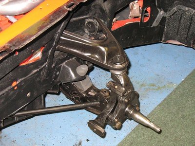
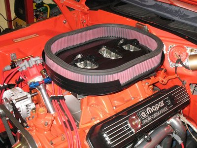
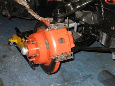
I banged the torsion bars all the way home on the suspension (a task that had hurt my head when last I tried) and then tackled how to mount the air cleaner unit.
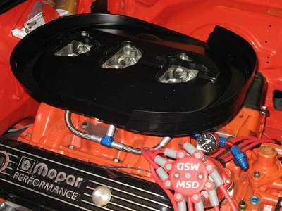
I have had to modify the air cleaner baseplate a little by cutting off the wide skirt that normally runs around the base.
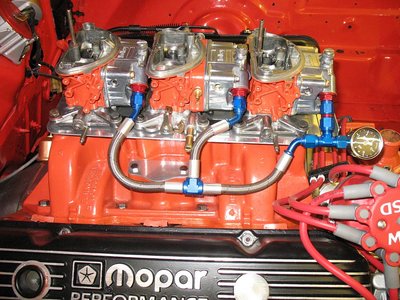
This was because the MSD dizzy and fuel pressure gauge were in the way of it.
Now I need to do is make a flat sheet metal top so that I have more clearence for the three inch tall filter.
The stock size K&N filter will not flow enough for a 440 at 6500rpm. So a taller filter is the only way I can go. This filter flows at least 900cfm of air. Ideal for me.
But because the engine does not centre in the engine bay I still need to modify the cross-brace under the power bulge hood, where it thickens at the passenger side, for a 1/2 inch more clearence there.
-

dave-r - Grumpy Old Man
- Posts: 9842
- Joined: 12 Oct 2003 21:45
- Location: North of the Tyne, England
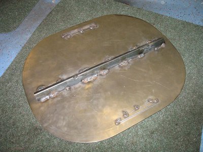
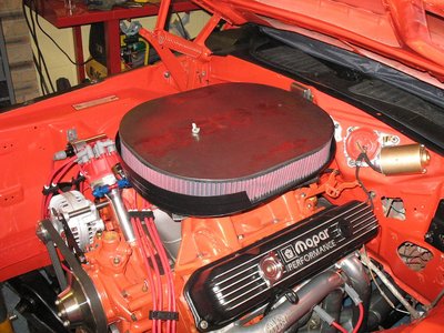
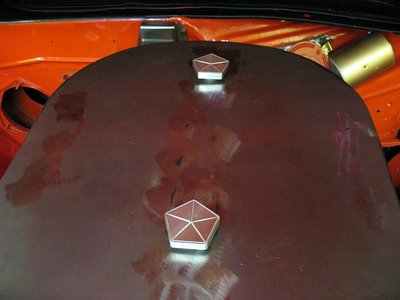
Today I made a lid for the air cleaner myself.
Flat 1mm steel. More headroom than the standard lid.
Going to paint it orange same as the old one was. Got some nice custom nuts to hold it down too. Need longer studs though.
The angle iron I welded to the inside serves three purposes.
First it stops the center of the lid bending down as I tighten the nuts.
Second it helps bend the air down into the carbs and fills what would be a low pressure void.
Third it acts to hold the filter out at the front and back. Same as the tabs on the sides. So the filter locks in place.
My welding hand was shaking badly. I mean really shaking. About a centimetre each way. But I managed to hit my targets eventually and get good, if not pretty, welds.
So it just needs a little filler and paint to finish that.
I want to use one of those big 440SIXPACK decals that went on the original lids. Just to finish it off.
Last edited by dave-r on 18 Apr 2008 9:25, edited 1 time in total.
-

dave-r - Grumpy Old Man
- Posts: 9842
- Joined: 12 Oct 2003 21:45
- Location: North of the Tyne, England
-

dave-r - Grumpy Old Man
- Posts: 9842
- Joined: 12 Oct 2003 21:45
- Location: North of the Tyne, England
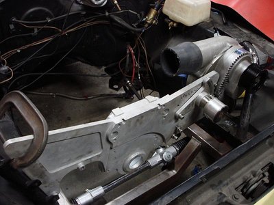
A lad called Trevor Dorrington in my car club does his own CNC machining. Motor plates, timing covers, air cleaner tops etc. Custom one offs to your spec and finishes either natural, polished, or anodised red or blue.
These air cleaner nuts are just a small sample of his work.
Email him if you want anything custom made for a really good price.
mopar@tesco.net
These air cleaner nuts are just a small sample of his work.
Email him if you want anything custom made for a really good price.
mopar@tesco.net
-

dave-r - Grumpy Old Man
- Posts: 9842
- Joined: 12 Oct 2003 21:45
- Location: North of the Tyne, England
-

Eddie - Frequent Poster
- Posts: 6212
- Joined: 16 Oct 2006 21:26
- Location: Terre Haute, Ind.
-

dave-r - Grumpy Old Man
- Posts: 9842
- Joined: 12 Oct 2003 21:45
- Location: North of the Tyne, England
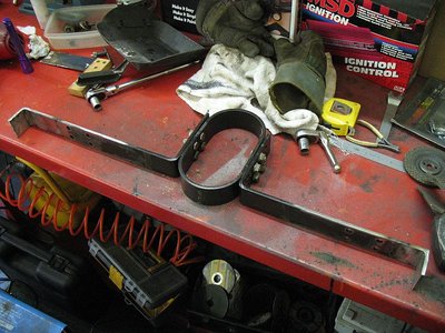
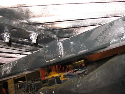
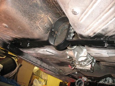
I haven't progressed the car much lately due to other matters getting in the way. But in the last couple of days I have been adding a little extra to the strength of the chassis.
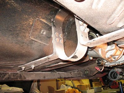
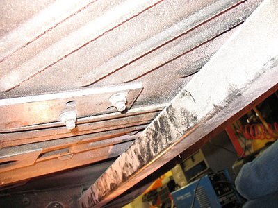
I already had these two simple chassis connectors in place for a number of years now. But have been meaning to tie them into the floorpan somehow for a long time.
As it happens, the driveshaft safety loop on my car is located 14-inches further to the rear than you would expect. This is because of the GV overdrive and shorter driveshaft.
However this puts the safety loop half way between the two ends of the chassis connectors, therefore half way between existing crossmembers, and on the flat bit of floorpan where they added the extra 2-inches over the Barracudas length.
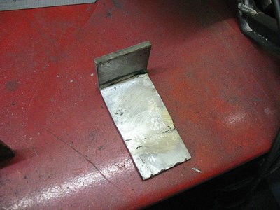
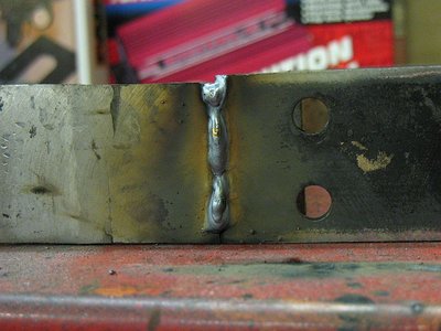
So I decided to extend the mounting brackets on the loop to reach the connectors, welding to them, and at the same time welding to the floorpan.
The safety loop is made from 1/4 steel so it is quite strong.
Because the trans tunnel does not run down the center of the floor, the drivers side of the loop mounting bracket needed extending more than the passenger side.
-

dave-r - Grumpy Old Man
- Posts: 9842
- Joined: 12 Oct 2003 21:45
- Location: North of the Tyne, England
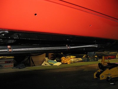
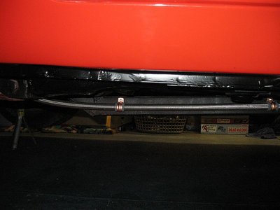
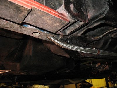
Here is my (almost) finished fuel line from the tank to the pump.
This is some hose I got cheap as it is 45thou larger diameter than normal hose. So normal AN hose ends you buy do not fit. However it came with one already crimped on so it was just a matter of running it to the half inch tank sender (yet to arrive) and secure with a clip.
Remember. There is no pressure in this hose. It is being sucked along by the mechanical pump so there is no pressure seal issues at the tank end.
I ran it though the frame rail at the front to avoid the header heat. If I had thought ahead I would have drilled a hole on the inside of the frame to exit the hose to the pump. But the engine is in the way now so it has to exit at the bottom and curve up.
I also added a heat shield where the hose passes the header primary pipes before the pump.
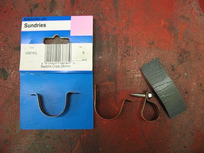
I made my own "P-clips" to fix the hose to the chassis.
-

dave-r - Grumpy Old Man
- Posts: 9842
- Joined: 12 Oct 2003 21:45
- Location: North of the Tyne, England
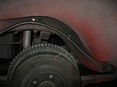
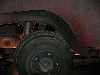
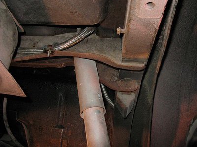
Moved the hose from the wheel well.
It now goes into the rear chassis leg, out of a new hole high up over the axle, over the shock crossmember, and along the crossmember past the back of the tank.
Much better.
It now goes into the rear chassis leg, out of a new hole high up over the axle, over the shock crossmember, and along the crossmember past the back of the tank.
Much better.
-

dave-r - Grumpy Old Man
- Posts: 9842
- Joined: 12 Oct 2003 21:45
- Location: North of the Tyne, England
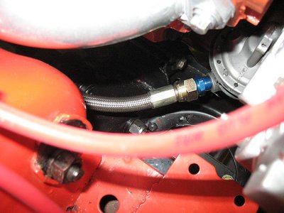
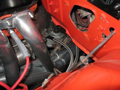
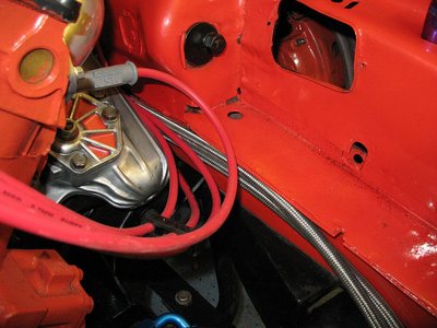
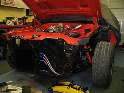
Transmission lines in.
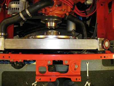
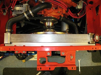
And I blocked off the gap i have at the top between the radiator and frame. A lot of air was shooting up there instead of through the radiator core. I could tell by all the flies stuck to the underside of the hood.
And I blocked off the gap i have at the top between the radiator and frame. A lot of air was shooting up there instead of through the radiator core. I could tell by all the flies stuck to the underside of the hood.
-

dave-r - Grumpy Old Man
- Posts: 9842
- Joined: 12 Oct 2003 21:45
- Location: North of the Tyne, England
-

dave-r - Grumpy Old Man
- Posts: 9842
- Joined: 12 Oct 2003 21:45
- Location: North of the Tyne, England
