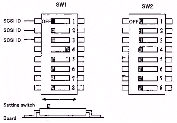
Figure 1 shows the type of switches and their settings when the drive was shipped.

Setting Switches(SW1,SW2)


Figure 1 shows the type of switches and their settings when the drive was

shipped.
Figure 1 Setting Switch (SW1,SW2) Switch SW1
SCSI data bus parity check Key 4 ON* Checkted OFF Not checked SCAM mode Key 5 ON Enabled OFF* Disabled Device type mode Key 6 ON Optical memory device (INQ='07') OFF* Direct access device (INQ='00') This determines what response the drive will give to an INQUIRY command. Spindle automatic stop mode Key 7 ON* Enabled OFF Disabled
With the disk loaded, the spindle continues to rotate until the START/STOP u nit command instructs the spindle to stop. The spindle automatic stop function comes into operation when the host does not issue a command for about 30 minut es. If the host issues a command after the spindle has stopped then the spindl e will start up and process the command without posting a not ready state. - This function greatly reduces the amount of dust that can collect on the dis k, however it is not suitable for a system which requires a quick response as the spindle takes several seconds to get up to speed. - The access monitoring time and the function itself can be changed or enabled via a MODE SELECT command.
LED mode Key 8 OFF* Mode1 ON Mode2
Mode1 The LED lights when drive is positioning, reading, writing, loading,e jecting and during the power on test. At power-on test the LED will blink at 1 second intervals after detecting an error or 2 second intervals having detecte d a themal error. Mode2 The LED lights only on power-on test and whilst waiting. Error detect ion and reporting is as for Mode1.
Switch Bank SW2
Verify mode Key 2 ON Disabled OFF* Enabled When disabled,the performance of a write operation is improved by approximatel y 20%, however data integrity cannot be guaranteed.
Mac mode Key 3 ON Enabled OFF* Disabled Because of the differing ways that both Apple Macintosh and PC hosts respond t o the status of the drive, set this switch accordingly. Mac mode ON will disab le the 'UNIT ATTENTION' reporting on power up and media change.
SCSI level Keys 4 5 OFF* OFF* SCSI-1 mode (Compatible with M2511A) ON OFF Not used OFF ON SCSI-2 mode ON ON Not used
SAVE DATA POINTER message mode Key 6 OFF* SAVE DATA POINTER message posted before sending DISCONNECT message ON No message sent before DISCONNECT messeage Key 7 OFF* Not used Key 8 OFF* Factory examination mode
Terminal CNH1
Terminal CNH2
 *1:This signal
indicates that the cartridge is in the drive. H:Exist L:None(TTL level
signal) *2:This signal is used for ejecting the catridge from the host
system *3:For the LED, the following specification must be satisfied. Format
current:20mA or less
Note:The cable length must not exceed 30cm.
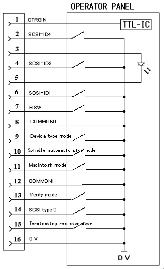
Figure 2 External operator panel circuit example
External operator panel connector Pin Signal 1 CTGIN (Catridge in) 2 -ID2 (bit value 4) 3 +LED (+5V) 4 -ID1 (bit value 2) 5 -LED 6 -ID0 (bit value 1) 7 EJSW (Eject switch) 8 COMMON 0 9 Device type mode 10 Spindle automatic stop mode 11 Macintosh mode 12 COMMON 1 13 Verify Mode 14 SCSI type 0 15 SCSI terminating resistor 16 0V(Ground)
The cable length to the operator panel should not exceed 30 cetimetres COMMON 0 and COMMON 1 are control signals and should not run to ground.
to the table of contents!!