Fujitsu M2903/M2909/M2915:Switch Settings
Setting Terminals
The user must set the following terminals and SCSI terminating resistor before
installing the HDD in the system.
Setting terminal:CN4, CN6, CN7, CN10
Figure 1 shows the setting terminal and the position of the SCSI terminating resistor modules.
- Notes:
- The user must not change the setting of terminals not described in this secction. Do not change setting statuses set at factory shipment.
- Do not change the setting of terminals except pin 5-6 of CN6(offline self-diagnostics)/pin 5-6 of CN7(write protect).
- To short the setting terminals, use the short plug attached when the device is shipped from the factory.
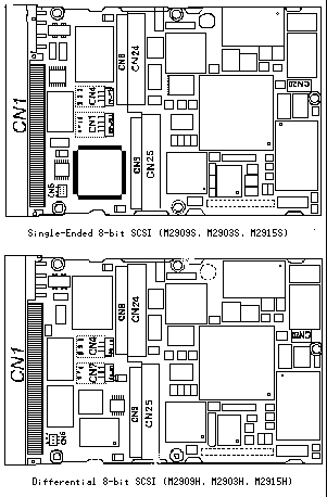
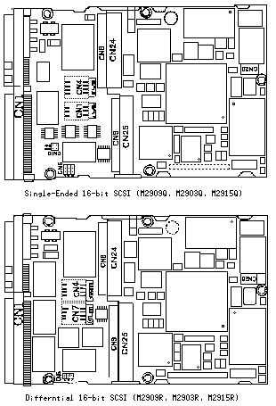
Figure 1 Setting terminal position
Setting terminals(CN4)
Figure 2 shows the setting terminals.
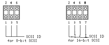
Figure 2 Setting terminals(CN4)
- Note:
- "Short" and "Open" in the explanation of this section have following meaning.
Short:The short plug is mounted between specified pins.
Open:The open plug is removed from between specified pins.
(1)SCSI ID
Table 1 and 2 list the HDD SCSI ID setting.
Table 1 8-bit SCSI SCSI ID setting(CN4)
| SCSI ID | 5-6 | 3-4 | 1-2 |
| 0 | OPEN | OPEN | OPEN |
| 1 | OPEN | OPEN | SHORT |
| 2 | OPEN | SHORT | OPEN |
| 3 | OPEN | SHORT | SHORT |
| 4 | SHORT | OPEN | OPEN |
| 5 | SHORT | OPEN | SHORT |
| 6 | SHORT | SHORT | OPEN |
| 7* | SHORT | SHORT | SHORT |
* Set at factory shipment
Table 2 16-bit SCSI SCSI ID setting(CN4)
| SCSI ID | 7-8 | 5-6 | 3-4 | 1-2 |
SCSI ID | 7-8 | 5-6 | 3-4 | 1-2 |
| 0 | OPEN | OPEN | OPEN | OPEN |
8 | SHORT | OPEN | OPEN | OPEN |
| 1 | OPEN | OPEN | OPEN | SHORT |
9 | SHORT | OPEN | OPEN | SHORT |
| 2 | OPEN | OPEN | SHORT | OPEN |
10 | SHORT | OPEN | SHORT | OPEN |
| 3 | OPEN | OPEN | SHORT | SHORT |
11 | SHORT | OPEN | SHORT | SHORT |
| 4 | OPEN | SHORT | OPEN | OPEN |
12 | SHORT | SHORT | OPEN | OPEN |
| 5 | OPEN | SHORT | OPEN | SHORT |
13 | SHORT | SHORT | OPEN | SHORT |
| 6 | OPEN | SHORT | SHORT | OPEN |
14 | SHORT | SHORT | SHORT | OPEN |
| 7 | OPEN | SHORT | SHORT | SHORT |
15* | SHORT | SHORT | SHORT | SHORT |
* Setting at factory shipment
- Notes:
- Set the SCSI ID so that there are no duplications between SCSI devices on the same SCSI bus.
- The priority of SCSI bus use in ARBITRATION phase is determined by SCSI ID as follows:
7>6>5>4>3>2>1>0>15>14>13>12>11>10>9>8
Setting terminals(CN6)
Figure 3 shows the type of setting terminals.
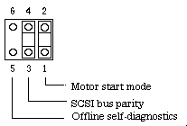 Figure 3 Setting terminals(CN6)
- Notes
-
- With respect to the setting terminals "short" and "open" mean the following:
Short:Jumper plug is set between specified pins
Open: Jumper plug is removed from specified pins
(1)Motor start mode
Set how to control the starting of the HDD spindle motor according to the Table 3. This setting only determines the operation mode when the power supply is turned on or the microcode is downloaded. In both modes, stopping or restarting the spindle motor can be controlled by specifying the START/STOP UNIT command.
Table 3 Motor start mode setting(CN6 1-2)
| Start timing of the spindle motor | 1-2 |
| Starting of the motor is controlled with the START/STOP UNIT command | OPEN |
| The motor is started immediately after the power supply is turned on or the microcode is downloaded | SHORT* |
* Setting at factory shipment
(2)SCSI bus parity
Set whether the SCSI data bus parity bit check is performed according to Table 4.
Table 4 SCSI bus parity setting(CN6 3-4)
| SCSI data bus parity check by HDD | 3-4 |
| Not performed | OPEN |
| Performed | SHORT* |
* Setting at factory shipment
(3)Offline self-diagnostics
Setting terminals CN5-6 are used to set starting/stopping the HDD offline self-diagnostics.(See Table 5). The offline self-diagnostics can test the normality of the HDD controller function and the basic read/write operation of the disk drive.
In normal opearation, the setting terminals must be open.
Table 5 Offline self-diagnostics setting(CN6 5-6)
| Offline self-diagnostics | 5-6 |
| Stopped(normal operation mode) | OPEN* |
| Executed(diagnostics mode) | SHORT |
* Setting at factory shipment
Setting terminals(CN7)
Figure 4 shows the types of seting terminals.
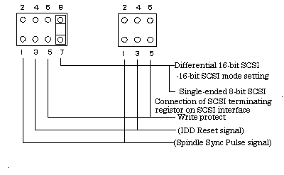
+ Single-Ended type, 8-bit SCSI  + Differential type, 8-bit SCSI
+ Single-Ended type,16-bit SCSI  + Differential type,16-bit SCSI

Figure 4 Setting terminals(CN7)
- Notes
- With respect to the setting terminal,"short" and "open" mean the following:
Short:Jumper plug is set between specified pins
Open: Jumper plug is removed from specified pins
(1)Write protect
Set setting terminals CN7 5-6 to enable or disable the write protect function provided for the HDD(See Table 6). When the write protect function is enabled, writing to the disk medium is disabled.
Table 6 Write protect setting(CN7 5-6)
| Write protect | 5-6 |
| Write operation is enabled | OPEN* |
| Write operation is disabled | SHORT |
* Setting at factory shippment
(2)Connection of the terninating resistor on SCSI interface(Single-Ended type, 8-bit SCSI)
Setting terminal CN7 7-8 set whether to use the terminating resistor circuit on the SCSI interface provided for the HDD. (See Table 7) The setting terminals enable the terminating resistor circuit to be connected on the SCSI interface. Only the HDD of the single-ended type is provided with the terminating resistor circuit. This setting is for single-ended type 8-bit SCSI.
Table 7 Setting the connection of terminating resistor on SCSI interface(CN7 7-8)
| Connection of the terminating resistor on the SCSI interface | 7-8 |
| Terminating resistor circuit is not connected | OPEN |
| Terminating resistor circuit is connected | SHORT* |
* Setting at factory shipment
(3)16-bit SCSI mode setting(Differential type, 16-bit SCSI)
Set setting terminal CN7 7-8 to enable or disable the 16-bit SCSI mode(See Table 8). When the 16-bit SCSI mode is enabled, all data bus (DB00 to DB15, DBP0 toDBP1) can be effective.
When the Differential type 16-bit SCSI HDD is used as 8-bit SCSI device, this setting must be open.
Table 8 16-bit SCSI mode setting(CN7 7-8)
| SCSI mode | 7-8 |
| 8-bit SCSI mode setting | OPEN |
| 16-bit SCSI mode setting | SHORT* |
* Setting at factory shipment
Setting terminals(CN10)
Figure 6 shows the types of the setting terminals
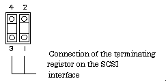
Figure 6 Setting terminals(CN10)(for single-ended type 16-bit SCSI)
- Note
- With respect to the setting terminal,"short" and "open" mean the following:
Short:Jumper plug is set between specified pins
Open: Jumper plug is removed from specified pins
Setting terminals CN10 1-2 and 3-4 set whether to use the terminating resistor circuit on the SCSI interface provided for the HDD(See Table 9). The setting terminals enable the terminating resistor circuit to be connected on the SCSI interface. This setting is for single-ended type 16-bit SCSI.
- Caution
- This setting is effective when the external operator panel(S6) is connected and pin A9 (TERM-ON) is open.
Table 9 Setting connection of the terminating resistor on the SCSI interface
(CN10 1-2 and 3-4)
| Connection of the terminating resistor on the SCSI interface | 3-4 | 1-2 |
| Terminating resistor circuit is not connected | OPEN | OPEN |
| Terminating resistor circuit is connected | SHORT* | SHORT* |
* Setting at factory shipment
Table 10 shows the setting of connection of the terminating resistor when the 16-bit SCSI model is used as 8-bit SCSI model.
Table 10 Setting connection of terminating resistor on SCSI interface
(CN10 1-2 and 3-4)
(Single-ended type 16-bit SCSI is used as 8-bit SCSI)
| Connection of the terminating resistor on the SCSI interface | 3-4 | 1-2 |
| Terminating resistor circuit is not connected | SHORT | OPEN |
| Terminating resistor circuit is connected | SHORT* | SHORT* |
* Setting at factory shipment
to the table of contents!!