14 posts
• Page 1 of 1
Engine Bay Progress Part III
![]() by cv70chall » 19 Aug 2011 14:31
by cv70chall » 19 Aug 2011 14:31
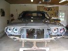
Onto the installation of the brake system, lines and some electrical wiring. Thanks Gary for the brake pedal linkage!
-
 Viewed 1295 times")
- Ready for wires and stuff.
-
 Viewed 1295 times")
- Adding lines.
-
 Viewed 1295 times")
- Brake system in.
-
 Viewed 1295 times")
- Battery/ Starter Wiring
-
 Viewed 1295 times")
- Linkage installed.
 Viewed 1295 times")
 Viewed 1295 times")
 Viewed 1295 times")
 Viewed 1295 times")
 Viewed 1295 times")
CVchall70
-
cv70chall - Frequent Poster
- Posts: 833
- Joined: 21 Oct 2006 20:15
- Location: Palm Beach, FL
-

MLMFLCN - Frequent Poster
- Posts: 238
- Joined: 10 Oct 2005 13:24
- Location: Ohio
Re: Engine Bay Progress Part III
![]() by burdar » 25 Aug 2011 15:07
by burdar » 25 Aug 2011 15:07
Looks like some good progress. Can I make a couple suggestions?
The small possitive battery cable wire should be bolted up the other way. Bolt it up from the front....don't loop it back like that. You won't have enough slack to hook the cable up to the battery. The cable then will get secured in white plastic straps. There should be a black plastic strap that hooks over the shock stud that also secures the possitive cable before it goes down into the metal bracket on the frame.
The upper control arm cam bolts should be installed the other way. Insert the bolts from the wheel well. The nuts should be visable in the engine compartment. That's how the factory did it and it will make life easier when the car is aligned.
There are a few other things you could do to make the engine compartment more factory correct but that's not a big deal. Not everyone cares about that. What you've done so far looks really good.
-
burdar - Frequent Poster
- Posts: 429
- Joined: 24 Mar 2009 17:27
- Location: Iowa
Re: Engine Bay Progress Part III
![]() by Adrian Worman » 25 Aug 2011 15:41
by Adrian Worman » 25 Aug 2011 15:41
burdar wrote:Looks like some good progress. Can I make a couple suggestions?
The small possitive battery cable wire should be bolted up the other way. Bolt it up from the front....don't loop it back like that. You won't have enough slack to hook the cable up to the battery. The cable then will get secured in white plastic straps. There should be a black plastic strap that hooks over the shock stud that also secures the possitive cable before it goes down into the metal bracket on the frame.
The upper control arm cam bolts should be installed the other way. Insert the bolts from the wheel well. The nuts should be visable in the engine compartment. That's how the factory did it and it will make life easier when the car is aligned.
There are a few other things you could do to make the engine compartment more factory correct but that's not a big deal. Not everyone cares about that. What you've done so far looks really good.
I agree, he's done a really good job so far, I'm well impressed, fast worker too
Jesus built my hot rod
-
Adrian Worman - Frequent Poster
- Posts: 2051
- Joined: 10 Mar 2007 23:54
- Location: milton keynes
Re: Engine Bay Progress Part III
![]() by DAYLEY/CHALLENGER » 26 Aug 2011 2:09
by DAYLEY/CHALLENGER » 26 Aug 2011 2:09
Looking good............go ahead and crimp the cover on the steering coupler seal.........its a real pain after the engine is in..............
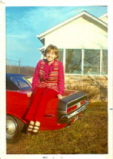
Avatar..Pic from 1971 showing my original 1970 Challenger and The Wife...Still My Inspiration today..
And My current project......
WEBSITE IS BACK UP...........
LINK http://www.papadaveonline.com/index.html
And My current project......
WEBSITE IS BACK UP...........
LINK http://www.papadaveonline.com/index.html
-
DAYLEY/CHALLENGER - Frequent Poster
- Posts: 229
- Joined: 14 Dec 2006 17:32
- Location: Rockingham, Nc ,USA
Re: Engine Bay Progress Part III
![]() by cv70chall » 26 Aug 2011 14:48
by cv70chall » 26 Aug 2011 14:48
Thanks for the thumbs up!
I am open to anything that'll make this look correct. I welcome advice!!
I will change the cable route and re-do the cam bolts as well. Can you provide a photo of exactly where that black fastening strap would go near the shock tower?
I will make sure we get that coupling fastened too. They are a pain in the ass, you know!
Thanks!!!
CVchall70
-
cv70chall - Frequent Poster
- Posts: 833
- Joined: 21 Oct 2006 20:15
- Location: Palm Beach, FL
Re: Engine Bay Progress Part III
![]() by burdar » 26 Aug 2011 18:41
by burdar » 26 Aug 2011 18:41
If you want the engine compartment to look more correct, here are a few things that need to be done....
First of all the 1970 master cylinder was a one year only unit. They are expensive if you can find them but the one you have will look fine. In 1970, the master cylinder and brake booster were assembled as a unit and were then painted black. So, the master and the lid should be black.
The power steering boxes should be painted black. The factory used cheap paint and it didn't stay black for very long. Manual boxes were left bare but the power boxes should be a slightly flatter black then the K-member.
The end of the steering column as well as the coupler were most often painted black. Some original cars have been found with unpainted ends but most were painted black.
Is that black plastic tubing hiding some aftermarket wiring? It might look better if you just left the wires exposed.
1970's also had the cowl blacked out. Some original cars have been found without the blackout but most cars(except the dark colored cars) had the cowl blacked out. Dave has a link in one of these sections to a Mopar Action article that shows the correct cowl blackout.
Finally, the tie rods, center link exc...were left bare metal from the factory...they weren't painted black.
Again, I'm not complaining or trying to put the car down. What you've done so far looks nice. Some people just care about originality more then others. Either way the car looks good. I've got some pictures of the battery cable strap on the shock stud but they are on another computer. I need to take some pics of my engine compartment anyway. I just installed that strap a couple days ago.
-
burdar - Frequent Poster
- Posts: 429
- Joined: 24 Mar 2009 17:27
- Location: Iowa
Re: Engine Bay Progress Part III
![]() by cv70chall » 26 Aug 2011 19:39
by cv70chall » 26 Aug 2011 19:39
I'm actually adding an aftermarket stereo and the loom is hiding some 4 gauge power cable.
CVchall70
-
cv70chall - Frequent Poster
- Posts: 833
- Joined: 21 Oct 2006 20:15
- Location: Palm Beach, FL
Re: Engine Bay Progress Part III
![]() by burdar » 27 Aug 2011 1:07
by burdar » 27 Aug 2011 1:07
Here's how my 73 is set-up. It will look a little neater once the battery and engine are installed. Right now the possitive cable is just hanging which pulls the rest of the wiring out of place.
 Viewed 1243 times")
-
burdar - Frequent Poster
- Posts: 429
- Joined: 24 Mar 2009 17:27
- Location: Iowa
Re: Engine Bay Progress Part III
![]() by cv70chall » 19 Sep 2011 20:51
by cv70chall » 19 Sep 2011 20:51
Thanks for the great tips!
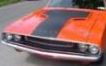
I've rearranged the cables and added the shock stud strap so it's correct. One question I have is the front mount section that houses the hood release/ spring and sits in front of the radiator. I have it painted body color- as I was under the impression that that piece (with the exception of the spring) is body color. Is that right?
I'm worried about the grille being argent/ black and having this section- which is orange- sticking out like a sore thumb.
I managed to also get the cowl blacked out and I think it came out ok. I actually used a large paint roller (measures about 16 inches in length) so I was able to get a straighter edge- even with the slight spray look.
Note: the paint is fresh and actually is flatter than it looks.
 Viewed 1215 times")
 Viewed 1215 times")
 Viewed 1215 times")
 Viewed 1215 times")
CVchall70
-
cv70chall - Frequent Poster
- Posts: 833
- Joined: 21 Oct 2006 20:15
- Location: Palm Beach, FL
Re: Engine Bay Progress Part III
![]() by dave-r » 20 Sep 2011 9:05
by dave-r » 20 Sep 2011 9:05
Nice.
From the front, the radiator support was only painted black in the area you can see through the grille and the opening below. The top of it (looking down) was body colour. There is a description and diagram on here somewhere...
From the front, the radiator support was only painted black in the area you can see through the grille and the opening below. The top of it (looking down) was body colour. There is a description and diagram on here somewhere...
The Dave giveth and the Dave taketh away.
-

dave-r - Grumpy Old Man
- Posts: 9842
- Joined: 12 Oct 2003 21:45
- Location: North of the Tyne, England
Re: Engine Bay Progress Part III
![]() by dave-r » 20 Sep 2011 9:18
by dave-r » 20 Sep 2011 9:18
"The front side of the radiator closure panel, below the top support (upper radiator "U" channel) and underneath the hood latch plate was painted Organasol Black. Overspray was permitted half way into the inside headlamp area."
This was not done on the dark colours of course.
This was not done on the dark colours of course.
The Dave giveth and the Dave taketh away.
-
dave-r - Grumpy Old Man
- Posts: 9842
- Joined: 12 Oct 2003 21:45
- Location: North of the Tyne, England
Re: Engine Bay Progress Part III
![]() by burdar » 21 Sep 2011 13:03
by burdar » 21 Sep 2011 13:03
Go buy a can of SEM Trim Black. It's a good quality paint and works perfectly for spraying the rad blackout. I like how you used the paint roller. The cowl blackout looks good.
-
burdar - Frequent Poster
- Posts: 429
- Joined: 24 Mar 2009 17:27
- Location: Iowa
Re: Engine Bay Progress Part III
![]() by cv70chall » 21 Sep 2011 21:03
by cv70chall » 21 Sep 2011 21:03
Thanks. I'll pick up that can tomorrow on my way into the shop.
CVchall70
-
cv70chall - Frequent Poster
- Posts: 833
- Joined: 21 Oct 2006 20:15
- Location: Palm Beach, FL
14 posts
• Page 1 of 1