I'm ready to start installing my painless wiring system, but need a little help on the start. The guide suggests I mount the block "inside on the drivers side". Pretty vague. It also suggests using the plate provided with a hole it it to run the engine wiring through (where the old fuse block used to be). I can't really mount the fuse block where it used to be because there would be significant gaps there.
Can anybody give me a good idea of where the best place would be to mount the new fuse block? If anybody has done this and has a picture, that would be greatly appreciated.
(very needy) Paul
21 posts
• Page 1 of 1
Help in getting started with the painless wiring system
![]() by The Toy Peddler » 23 Jan 2010 18:02
by The Toy Peddler » 23 Jan 2010 18:02
- The Toy Peddler
- Frequent Poster
- Posts: 137
- Joined: 01 Feb 2009 16:26
- Location: Grants Pass, Oregon
![]() by dave-r » 23 Jan 2010 19:16
by dave-r » 23 Jan 2010 19:16
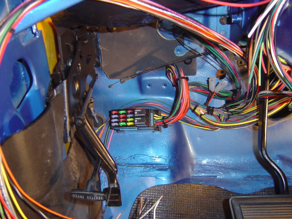
Well i was still pretty brain damaged when I did mine and I made some strange decisions as a result but anyway I decided to not fit it where the original fuse box was and placed it here as you see in the photo below.
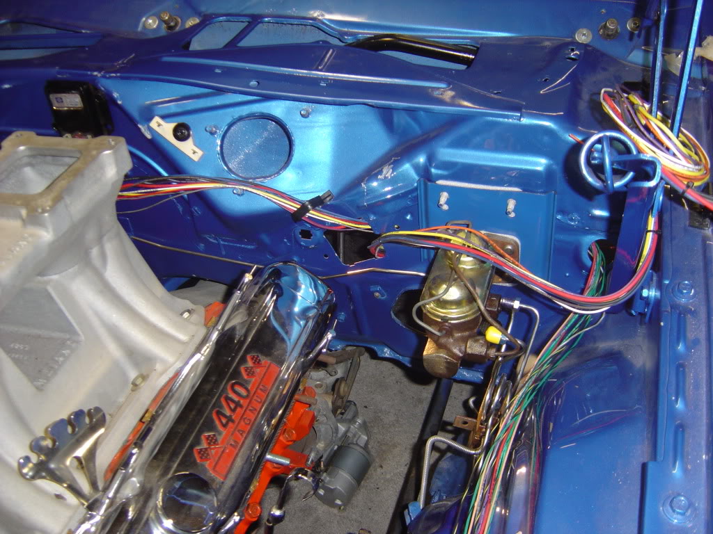
One reason for fitting it there was because most of my wiring was not going through the firewall where the fuse box was. I ran most of my engine bay wiring along the inside of the front fender to an electrical panel I fabricated where the battery used to be. So the forward harness exits through the bulkhead into the wheel well and not the engine compartment.
The metal plate you see on the right here, not only blanks off the hole for the old bulkhead connector, but also mounts the brake line lock solenoid on the other side of it.
You would have to go though the thread on my build in the photos section to see more details.
 Viewed 1310 times")
-

dave-r - Grumpy Old Man
- Posts: 9842
- Joined: 12 Oct 2003 21:45
- Location: North of the Tyne, England
![]() by The Toy Peddler » 23 Jan 2010 19:53
by The Toy Peddler » 23 Jan 2010 19:53
This is pretty funny. After going out and deciding it will NOT be going through the original fuse block hole, I mounted it almost exactly where you did! (before seeing your reply) Maybe about 1/2 in. lower so I can still access it just below the vent. I will run my headlight wiring in the hole I have almost directly above that and will run my main engine, wiper motor and washer, and horn wires through the plate I will place in the original fuse block area. I've already run all the wires to the rear and just have to seperate the dome light and sending unit wires and that should do it for the rear section. This is going to be easier than I thought. At least for now! I'll probably have to back up somewhere along the line though.
I didn't permanently affix the fuse block, but just drilled the holes and started threading the screws leaving them loose. I figure I will get them tightened down after I install the carpet.
I'll take a few pics as soon as my camera battery charges up.
Paul
I didn't permanently affix the fuse block, but just drilled the holes and started threading the screws leaving them loose. I figure I will get them tightened down after I install the carpet.
I'll take a few pics as soon as my camera battery charges up.
Paul
- The Toy Peddler
- Frequent Poster
- Posts: 137
- Joined: 01 Feb 2009 16:26
- Location: Grants Pass, Oregon
![]() by dave-r » 24 Jan 2010 10:29
by dave-r » 24 Jan 2010 10:29
I remember now. I saw that flat area just above your fuse box in your first photo there (with the two pre-marked dimples for drilling and fitting a clutch?) and thought that would be a neat place to put it.
-
dave-r - Grumpy Old Man
- Posts: 9842
- Joined: 12 Oct 2003 21:45
- Location: North of the Tyne, England
![]() by The Toy Peddler » 24 Jan 2010 15:20
by The Toy Peddler » 24 Jan 2010 15:20
I almost did that too, but I wasn't sure if something else went there and besides, it didn't look like there would be enough room under the vent to access it later. I'll probably attach all the rear lights and dome light today and start working some of the accessories.
Can you tell me where the sending unit wire (blue) goes through the floor? There is a hole way over by the filler line but that seems to be a long route for that wire.
I hope I'm not bugging you too much with all these questions, but right now you are my No.1 resource for these things. I have the complete shop manual and also wiring diagram, but it doesn't tell you everything.
Paul
- The Toy Peddler
- Frequent Poster
- Posts: 137
- Joined: 01 Feb 2009 16:26
- Location: Grants Pass, Oregon
 Viewed 1312 times")
![]() by The Toy Peddler » 24 Jan 2010 16:08
by The Toy Peddler » 24 Jan 2010 16:08
Mine is a replacement also and there is no hole in that area. The only hole is about 18" right of that and is about a 1 1/2" hole that will need a large grommit to fill. I might just drill a hole in that area and use a very small grommit. I'm sure glad I'm not making one of those restores that every nut, bolt and placement has to be correct. That is a bit anal if you ask me, but for those guys that have something that is totally original, it's cool. This is definitely NOT a survivor car, although it was nearly pronounced dead at one time!
Paul
Paul
- The Toy Peddler
- Frequent Poster
- Posts: 137
- Joined: 01 Feb 2009 16:26
- Location: Grants Pass, Oregon
![]() by drewcrane » 24 Jan 2010 16:49
by drewcrane » 24 Jan 2010 16:49
The Toy Peddler wrote:Mine is a replacement also and there is no hole in that area. The only hole is about 18" right of that and is about a 1 1/2" hole that will need a large grommit to fill. I might just drill a hole in that area and use a very small grommit. I'm sure glad I'm not making one of those restores that every nut, bolt and placement has to be correct. That is a bit anal if you ask me, but for those guys that have something that is totally original, it's cool. This is definitely NOT a survivor car, although it was nearly pronounced dead at one time!
Paul
yes mine is a replacement and i put the hole (with a grommet) in the most practical place and then i looked at my wifes car and it was close enough,for government work, but not in the exact place the factory did,and mine to was a throw away car ! .............until i got it
-

drewcrane - Frequent Poster
- Posts: 2893
- Joined: 01 Sep 2007 12:36
- Location: "follow the laraya belt ,that should get ya there"
![]() by The Toy Peddler » 24 Jan 2010 21:13
by The Toy Peddler » 24 Jan 2010 21:13
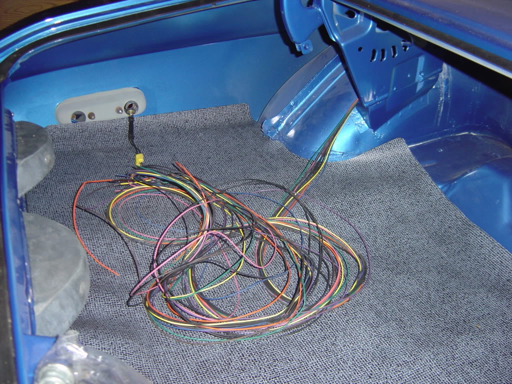
Got the hole drilled, grommit in place and wire running through. This painless wiring system is working pretty good so far, but I've really only run the groups to their respective places, except for the rear section, which was a breeze. I've tie wrapped them, cut the wires for all lights, and am ready to install clips and pigtails for the lights. One question for Dave, since you have aleady done this: In the trunk section, there is an orange wire marked "third brake light". Does this also connect to the back up light (clear) for a "third" brake light? Also, there is no wire for the trunk light. Do I just need to run one all the way back or can I splice off the dome light or something?
This board is really a life and time saver!
Paul
This board is really a life and time saver!
Paul
- The Toy Peddler
- Frequent Poster
- Posts: 137
- Joined: 01 Feb 2009 16:26
- Location: Grants Pass, Oregon
![]() by The Toy Peddler » 25 Jan 2010 0:05
by The Toy Peddler » 25 Jan 2010 0:05
One more question....(then probably one more and .....) The pigtails on the side lights have a female and a male end. I only have 1 wire going to them. How does that work?
Paul
Paul
- The Toy Peddler
- Frequent Poster
- Posts: 137
- Joined: 01 Feb 2009 16:26
- Location: Grants Pass, Oregon
-
dave-r - Grumpy Old Man
- Posts: 9842
- Joined: 12 Oct 2003 21:45
- Location: North of the Tyne, England
![]() by The Toy Peddler » 25 Jan 2010 13:17
by The Toy Peddler » 25 Jan 2010 13:17
I think I found it. One side is a ground which they don't supply. I also have the remnants of my old wiring harness and will look at that today.
Thanks again for the help. I will probably need some more this week.
We are planning on installing the headers today. We had a little delay in getting the hoist here. It should move pretty quickly after that. I can hook up the wires to the starter, distributor, and alternator and then move on to hooking up the hoses and fuel line. I still need to fab some brackets for the radiator which is oversized for the opening, but since the entire engine bay is already painted, I didn't want to cut and replace those. It should work with a little ingenuity.
- The Toy Peddler
- Frequent Poster
- Posts: 137
- Joined: 01 Feb 2009 16:26
- Location: Grants Pass, Oregon

![]() by dave-r » 25 Jan 2010 19:53
by dave-r » 25 Jan 2010 19:53
Here is a list of the bits not included in the kit.
But keep in mind I only had 60% of my brain functional at the time I did this.
Wires not included;
Starter Relay to Starter Solenoid
Green wire from Regulator to Alternator field
Windscreen Washer wiring
Blower motor wiring
Neutral Safety Switch wire
Clock wiring
Emergency brake light wiring
But keep in mind I only had 60% of my brain functional at the time I did this.
Wires not included;
Starter Relay to Starter Solenoid
Green wire from Regulator to Alternator field
Windscreen Washer wiring
Blower motor wiring
Neutral Safety Switch wire
Clock wiring
Emergency brake light wiring
-
dave-r - Grumpy Old Man
- Posts: 9842
- Joined: 12 Oct 2003 21:45
- Location: North of the Tyne, England
![]() by The Toy Peddler » 26 Jan 2010 0:26
by The Toy Peddler » 26 Jan 2010 0:26
That's really helpful. I found I have to run several ground wires that weren't included. I also have to scrounge the light sockets from my old harness, which luckily are all there and in pretty good shape.
- The Toy Peddler
- Frequent Poster
- Posts: 137
- Joined: 01 Feb 2009 16:26
- Location: Grants Pass, Oregon
-
dave-r - Grumpy Old Man
- Posts: 9842
- Joined: 12 Oct 2003 21:45
- Location: North of the Tyne, England
Re: Help in getting started with the painless wiring system
![]() by DaveNWT » 14 May 2012 3:09
by DaveNWT » 14 May 2012 3:09
How did you guys wire in your guages? , i am having some trouble with that.
- DaveNWT
- Posts: 1
- Joined: 14 May 2012 2:56
Re: Help in getting started with the painless wiring system
![]() by dave-r » 14 May 2012 7:33
by dave-r » 14 May 2012 7:33
What exactly are you struggling with?
Remember that some of them take 5v power from the low voltage supply on the back of the cluster. So you take battery power to the little 5v supply unit and the Painless harness has the signal wires for each gauge.
Remember that some of them take 5v power from the low voltage supply on the back of the cluster. So you take battery power to the little 5v supply unit and the Painless harness has the signal wires for each gauge.
The Dave giveth and the Dave taketh away.
-
dave-r - Grumpy Old Man
- Posts: 9842
- Joined: 12 Oct 2003 21:45
- Location: North of the Tyne, England
21 posts
• Page 1 of 1