Page 1 of 1
Wiring assumption......horn wire.

Posted:
22 Jan 2010 23:13by The Toy Peddler
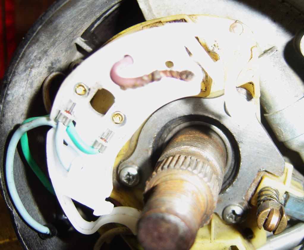
While replacing the turn signal cancellation piece on the steering column, I noticed a loose wire that was just looped back through the hole in the cancellation piece and not connected to anything. I then noticed a place on the horn "ring" that appeared to have been soldered but had no wire attached. The pinkish wire in the center of the photo is the one in question. Is this supposed to be wired to the ring? The picture of the ring got a bit over exposed, but in the bottom right there is the spot that appeared to have a wire attached.
Am I assuming correctly that this wire should be soldered to the ring?
As always your help is much appreciated.
Paul


Posted:
23 Jan 2010 4:10by drewcrane
ya know i myself had had some fire/ground issues in the s.column,and from the pix, i cant see alot ,but from what you say(soldering/wires that go no where) you need to look at your factory wiring diagram,
if you dont have that, i have one right here, also if you can take a better pic so i can see the wire better the pinkish wire is it actually violet?
because the 3 wires on my diagram for the horn are dark green,violet, and black
,now this may not mean anything because i have changed my wires, but get a better pic , or description of the color
or a good look at the color of the wire, and post it here, also just hook up the battery and see if the horn works,
Am I assuming correctly that this wire should be soldered to the ring?
yes that is the horn ring and a wire needs to be attached for the horn to work,
this all needs to have a good ground

Posted:
23 Jan 2010 11:35by dave-r
No that is not right. I just had mine apart as well but can't remember how it goes. That little brass wheel is the electrical contact with the ring. Someone has had a right do at the wiring in there and messed it up.

Posted:
23 Jan 2010 14:48by The Toy Peddler
It is definitely the violet wire. There is no other loose wire in the area and no wire attached to the horn ring.
So: The horn ring is supposed to have a wire soldered to it...correct?
When I took this apart the violet wire actually went back through the small hole seen in the cancellation piece but was not connected to anything. It sat there by the 2 thin wire pieces on the underside of the cancellation piece, which I am sure was not correct.
I can't try this out just yet, as ALL wiring except for the steering column has been removed from the car and I am about to start installing the painless harness.

Posted:
23 Jan 2010 14:59by drewcrane
i have to take mine apart anyway today since the turn signal arm is loose, if it isnt too cold i will check it today, but that pic of that wire coming through doesnt look right for some reason but i will look today


Posted:
24 Jan 2010 19:06by drewcrane
ok this is what i have working on my car,
this a later model replacement but it does the same thing,
if painless does not have a steering harness you should replace the one you have , here are some pix


Posted:
24 Jan 2010 19:50by The Toy Peddler
Now I'm confused. I have the brass ring, but not the larger ring that the wire is coming through. The wire in my photo looks to be the same one in yours that is a lavender/pinkish color. Yours looks like it goes down through the turn cancellation switch, but then were does it connect to? Mine was just sitting loose after it went through the hole.
Thanks for the help.
Paul

Posted:
24 Jan 2010 21:48by drewcrane
, that ring should have the wire connected to it so that it can go up through the hub and connect on the horn button,on the steering wheel, the pink wire goes to the flasher,from what my diagram says, see if the flasher has a pink wire connected to it,from your ,and what you are saying that pink wire is not connected at either end right?
Re: Wiring assumption......horn wire.

Posted:
17 Jan 2012 16:04by cv70chall
Can anyone tell me what the SINGLE YELLOW wire is for that comes out of the steering column? It has a round female plug on the end of it. I do not have the keylight lamp on the column so I don't think it's for that.

Thanks!
Re: Wiring assumption......horn wire.

Posted:
17 Jan 2012 18:26by fbernard
Lokking at the wiring diragram for 1970 and 1971, I see that the single yellow wire is labelled "IGNITION LT." for 1970 and "COURT LT." for 1971.
That sounds awfully like the courtesy light, doesn't it?
It's on the "schematic B" for both years, right between the turn signal switch connector and the ignition switch connector.
Most yellow wires on the schematic appear to be related to the map light/courtesy light/door switches and such.
http://www.mymopar.com/downloads/1970/70ChallengerB.JPGhttp://www.mymopar.com/downloads/1971/71ChallengerB.JPG


