31 posts
• Page 1 of 2 • 1, 2
Problems with swapping to a chrome box
Hey guys, need your help. I just swapped my factory module box and coil to the chrome module box and a msd blaster 2 coil. Easy change I thought... But when I wanted to start the car for a testdrive, the following happens. As soon as I turn the key to the "before crank position" my RPM gauge went to about 4500rpm and the longer I waited the higher it reached. Also while doing this I hear a buzzing noise from under the hood. I listened, but I cant tell where it's from. I don't think this is a good thing so I thought I ask you guys for help. I do know for almost 100% that the positive/negative wiring at the coil is done right.
Hope anybody can help me out here, thnx in advance
Hope anybody can help me out here, thnx in advance
- Hans
Problems with swapping to a chrome box
It starts as it should do, the buzzing is away when started. BUT, before starting as said the rpm gauge points at about 4500rpm and goes higher when the key sits in before crank position. After I let it run for a couple of minutes and put it out and the key back in the before crank position again it shows about 5000rpm. So when the car's running it's not buzzing and the rpm gauge works as normal but meanwhile it's building up voltage at the rpm gauge or something like that...cause it's showing a higher rpm then in the beginning. Can't understand why, maybe you...
- Hans
Problems with swapping to a chrome box
I have on occasion heard a crackling noise from my dizzy. Maybe twice. Whenever I try to reproduce it it will not do it. I use a Jacobs unit. Maybe when the reluctor is perfectly in line for firing?
Does it still do it now it has been cranked?
Do MSD not have a tech line on the web?
Does it still do it now it has been cranked?
Do MSD not have a tech line on the web?
- dave-r
Problems with swapping to a chrome box
If the coil is firing (causing the buzzing) you will get an RPM reading. That will not damage the tach.
- dave-r
Problems with swapping to a chrome box
I don't understand your 1st 2 lines Dave... and yes it still does now it has been cranked. I thougt maybe it's the resistor, I have bought a resistor specially for the chrome ignition box. Maybe when I have installed it it's over.. But I don't know how to install, cause the stock resistor has 4 wires connected to it, and this new can only have 2 wires...so I have to convert some things. Only I do not know how, therefore I need the help of a friend of mine who has been dragracing for 25 yrs including a 340 challenger. Ran 10.99 with that smallblock! He proparbly knows how to do it. But suggestions are always welcome as you know...
But it doens't hurt the tag Dave (it's getting higher and higher when cranking or driving etc.) so I can drive with it?
Thanks
But it doens't hurt the tag Dave (it's getting higher and higher when cranking or driving etc.) so I can drive with it?
Thanks
- Hans
Problems with swapping to a chrome box
It's not hurting the tach but it maybe hurting something else. I can't think what the problem might be but one thing is for sure and that is you need to change that ballast resistor.
- dave-r
Problems with swapping to a chrome box
Any experience with converting the stock 4wires ballast resistor to a 2wires resistor ? Will do that first I think. Thanks so far Dave.
- Hans
Problems with swapping to a chrome box
I have done it once on a mates car a few years ago Hans. I can't remember how they are wired now. I will have to read up on it. I'll get back to you tonight.
- dave-r
Problems with swapping to a chrome box
OK here goes. It might help to look at the bit I wrote about electronic ignitions elswhere in this section. I can't tell you how this hooks into the MSD system as I don't have one but this is how the stock ignition should hook up.
Disconnect your battery.
Remove your old ballast resistor and fit the new one in it's place.
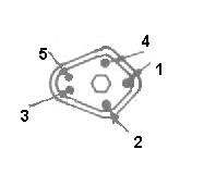
Look at this diagram it is the view of the rubber plug that fits onto the chrome box. I did the drawing so that it is the same as looking at the contacts inside of the plug when you pull it off and turn it over.
There should be two wires coming off pins 4 and 5 that go to the connector on the distributor yes?
Take the (green?) wire from pin 3 and cut it off.
The wire from pin 2 should go to the negative of the coil.
Pin 1 is connected to one end of the ballast resistor.
The coil positive should be connected to the other end of the resistor.
Now we have to sort out the remaining wires (the tricky bit).
I don't know how many wires you have because sometimes they are connected together elsewhere before they get to the resistor so you need to check with a meter to see where they connect to.
But you want the alternator field, voltage regulator, and the wire coming from ignition 1 (run) connected to the same side of the resistor as the wire from pin 1 on the connector.
On the other end with the lead from the positive of the coil you want a wire from the other position on the switch (ign 2) which is the position when cranking the engine. This may be a brown wire.
Also make sure you have a good connection between the chrome box case and earth.
I hope this makes some kind of sense.
Disconnect your battery.
Remove your old ballast resistor and fit the new one in it's place.
Look at this diagram
 it is the view of the rubber plug that fits onto the chrome box. I did the drawing so that it is the same as looking at the contacts inside of the plug when you pull it off and turn it over.
 There should be two wires coming off pins 4 and 5 that go to the connector on the distributor yes?
Take the (green?) wire from pin 3 and cut it off.
The wire from pin 2 should go to the negative of the coil.
Pin 1 is connected to one end of the ballast resistor.
The coil positive should be connected to the other end of the resistor.
Now we have to sort out the remaining wires (the tricky bit).
I don't know how many wires you have because sometimes they are connected together elsewhere before they get to the resistor so you need to check with a meter to see where they connect to.
But you want the alternator field, voltage regulator, and the wire coming from ignition 1 (run) connected to the same side of the resistor as the wire from pin 1 on the connector.
On the other end with the lead from the positive of the coil you want a wire from the other position on the switch (ign 2) which is the position when cranking the engine. This may be a brown wire.
Also make sure you have a good connection between the chrome box case and earth.
I hope this makes some kind of sense.
- dave-r
Problems with swapping to a chrome box
If you have this right you should have battery voltage going straight to the coil positive when cranking and voltage via the resistor when the ignition switch is in the normal (run) position. You should also have battery voltage going to pin 1 on the ignition box as well as to the voltage regulator and the alternator field circuit when in the run position.
- dave-r
Problems with swapping to a chrome box
Thanks Dave, but I don't think this makes any sence to me... I have totally no experience with ignition systems/electrical things so I think I will stick with the orange box till I know for sure how to wire everything up before I •••• up the whole system. But thanks again Dave, I just printed this message to remember it for later on.
- Hans
Problems with swapping to a chrome box
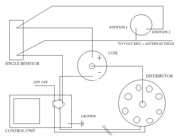
Dave, I think I know how it should be... check this:

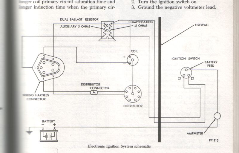
If this is right and I would compare it with the stock schematic pic out of the original service manual (should had a look it sometime earlier) it would mean the following: I have to replace the stock dual ballast resistor for the single one I have and cut off the wire you mentioned. Nothing more then that?
Then I have to contact all the leads which are now contacted to the upper 2 contact points of the stock dual resistor to the upper contact point of the new single resistor
and
the leads which are contacted to the lower 2 contact points of the stock dual resistor to the lower contact point of the new single resistor besides the 'green?' wire from the control unit which I have to cut off.
Am I right on this Dave (can you understand this kind of english) or am I talking **** ??
- Hans
Problems with swapping to a chrome box
Your drawing is right hans. I don't know what leads are connected at your dual resistor. You will have to trace them.
- dave-r
Problems with swapping to a chrome box
I looked in a very old book I have last night and found circuit diagrams of dual resistors etc. I will study it tonight and let you know.
It is still better to trace the wires with an ohm meter because it has been many years since the car left the factory and they may have been mixed up at some point.
It is still better to trace the wires with an ohm meter because it has been many years since the car left the factory and they may have been mixed up at some point.
- dave-r
Problems with swapping to a chrome box
Dave, this would mean that if my car is wired up like our schematics it would be easy to install the single resistor by just following the wires to look if they're like the schematic and then do the things you described somewhere above. You're SURE about the instructions you gave me aint you Dave... Looks like a nice saterday job.
Thanks Dave, problems are clearing up because of you!
Thanks Dave, problems are clearing up because of you!
- Hans
Problems with swapping to a chrome box
Go for it Hans!
Just to confuse you when you thought you had it all figured out.....

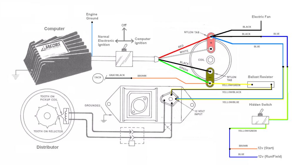
This is how my ignition system is wired. Ignore the colour of the wires. I am a sloppy worker and those wires were what I had lying around!
The main difference with mine is that the wires do not go to the coil but to the Jacobs unit first. Then back to the coil. The plastic tabs that come with the Jacobs unit and fitted on the coil terminals allow this.
The other big difference is that on mine I have the ballast resistor in a different part of the circuit. This was to deliver full battery voltage to the Jacobs unit. The resistor is now on the other side of the coil but electrically this amounts to the same thing. This gives the right voltage at pin 2.
In my system it is the Jacobs unit that determins the voltage and current in the coil - not the ballast resistor. Your MSD system might work the same way which is why I have posted this.
But don't let me confuse you!
Just to confuse you when you thought you had it all figured out.....

This is how my ignition system is wired. Ignore the colour of the wires. I am a sloppy worker and those wires were what I had lying around!
The main difference with mine is that the wires do not go to the coil but to the Jacobs unit first. Then back to the coil. The plastic tabs that come with the Jacobs unit and fitted on the coil terminals allow this.
The other big difference is that on mine I have the ballast resistor in a different part of the circuit. This was to deliver full battery voltage to the Jacobs unit. The resistor is now on the other side of the coil but electrically this amounts to the same thing. This gives the right voltage at pin 2.
In my system it is the Jacobs unit that determins the voltage and current in the coil - not the ballast resistor. Your MSD system might work the same way which is why I have posted this.
But don't let me confuse you!
- David Robson (Admin)
Problems with swapping to a chrome box
I just spotted something with mine. It might be better for the tach to get it's signal from the other side of my ballast resistor. I will look into that.
- dave
Problems with swapping to a chrome box
"But don't let me confuse you!" ...
You don't just confuse me, you drive me nuts. Now I don't get it anymore... I think I just stick to the first couple of pics and schemes. These are right to, ain't it Dave... Your 'Jacobs' pic looks totally diff to me, more/diff wires to other points?¿?¿
Just one question Dave: are you sure about the first schemes with cutting of the green wire etc.? If so, I will go for it this weekend!
- Hans
Problems with swapping to a chrome box
something is wrong here, the orange box uses the same exact wiring as the chrome box.
- ted
Problems with swapping to a chrome box
That is right Ted. Neither units use a dual ballast resistor and the green wire is not used.
Hans. If you are worried about it just do not connect the green wire and tie it up out of the way. Use the first two drawings and ignore my sytem.
Hans. If you are worried about it just do not connect the green wire and tie it up out of the way. Use the first two drawings and ignore my sytem.
- dave-r
Problems with swapping to a chrome box
Ted.
I don't know why he has the problem that started this thread. But before trying to find out what is wrong we have to get the wiring as it should be. Hans has not used the ballast resistor that came with the chrome box and so we need to get that right first and check that all the other wires are where they should be.
Hans.
Ignore the bit where I say "Your MSD system might work the same way which is why I have posted this." I forgot for a minute that you are just trying to fit an MSD coil and not an MSD ignition system. Too many things on my mind at the moment!
- dave-r
Problems with swapping to a chrome box
Looks like we solved another problem guys! Everything's installed, no buzzing noise and it seems that everything is working. But I still have to testdrive it this noon I think. I will try to explain everything I've done later on.
- Hans
Problems with swapping to a chrome box
Everything taped in again, and back was the buzzing noise...damn I thougt. Now I found out that it has only something to do with the grounding of the chrome box. The chrome unit needs much more ground than the orange one. With the orange one bolted on the firewall everything works okay but when I throw in the chrome one at the same place (like where it's originally installed) I hear the noise again. Now when I lay the chrome box just loose at the header there's no noise and everything is working fine. So therefore my conclusion about that ground thing. But now I need to find something to get a good ground. Just an electricity wire to the chassis won't work either. Ideas?
So I removed the tape and checked al the wires for nothing... just some good ground! But at least now I know something more about the ignition system/wiring...
So I removed the tape and checked al the wires for nothing... just some good ground! But at least now I know something more about the ignition system/wiring...
- Hans
Problems with swapping to a chrome box
That wire I told you to cut off Hans? Take that to a good ground. That might do it.
Otherwise scrape a bit of paint off around the screw holes in the bulkhead, clean the same area on both sides of the chrome box, smear on a bit of grease on the bare metal, and screw it onto the bulkhead nice and tight.
Make sure you use good connectors where any wires join. Don't just twist wires together once it is working.
- dave-r
Problems with swapping to a chrome box
Nothing works. I have spend more time to search/try a good ground then I spend on installing the resistor and checking the wiring. If I lay the box at the header or inside (from underneath) the hood it's working great, but as soon as I try it with a copper wire (1mm thick) from the box to the places named before it's going to make the noise again. It's not caused by the connectors, there are only a few there which are good. I even 'cleaned' the firewall at the spot where the box attaches to it till blank steel appears, but still nothing. I would think a firewall makes a good ground...
- Hans
Problems with swapping to a chrome box
Just a thought. May be nothing in it. But how good is your engine-to-chassis earth. If it works when touching the engine but not the chassis that may be it.
- dave-r
Problems with swapping to a chrome box
It's not as I thought it was... this is how it is:
- It was wired like it originally should be.
- The single resistor is installed
- The noise is caused by electricity jumping over from the chrome box to the ground (firewall)
- It all works fine when the chrome box lays at the header/valve cover bolts and then it starts good.
- When layed on or to the firewall or hood the noise is back again but the engine starts good.
- When layed on some hoses it doesn't make the sound but it does not start either. (no ground)
So it does look like it has something to do with the grounding thing. You could be right Dave about the engine to chassis earth. Sorry to ask, but how to check or make a new engine to chassis earth without some meters... (don't have a voltmeter or something)
But then I still can't figure out why everything works great with the orange box and not with the chrome one cause as Ted said, they are wired the same way...
- Hans
31 posts
• Page 1 of 2 • 1, 2
