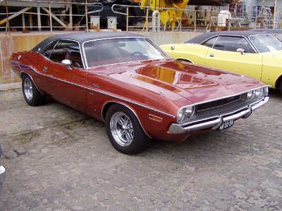
Chrysler Corporation were the first major manufacturer to start fitting electronic ignitions as standard in 1972-73 but they had been around for years before that.
Electronic ignitions work in exactly the same way as a point system - only much better. Where as the points are a mechanical switch the transistor in an electronic ignition is an electrical switch.
There are three factors which determine how well a points switch works;
1) How much current it can interrupt (bigger is better)
2) How fast it can interrupt this current (smaller is better)
3)How long it allows current to build up (dwell angle, bigger is better)
Even the most basic type of electronic ignition is a great improvement over normal points because of the faster switching speeds, big power handling capability and huge dwell angles.
The electronic ignition is made up of three parts;
1) THE RELUCTOR
This is a rotating magnet with "teeth" on it (like a gear wheel) corresponding to the number of cylinders the engine has. As it rotates, its teeth pass very close to the pick-up coil and causes the magnetic field in that coil to go up and down.
The reluctor has the same function as a distributor cam and often sits in its place.
2) THE PICK-UP COIL
This is a small wire coil which sits close to the reluctor. As the reluctor rotates, a voltage spike is induced into this coil by the reluctors magnetic field which tells the transistor in the amplifier when to interrupt the primary current in the ignition coil.
The pick-up coil takes the place of the rubbing block in a points system.
3)THE AMPLIFIER
This is actually the wrong name for what it does. The current to the coil is not amplified in this type of system. All that happens is that when it senses a voltage spike from the pick-up coil, the amplifier switches off the current to the ignition coil primary winding creating a spark from the coil.
The amplifier is the equivalent of the contact points.
Some systems use an optical device to trigger the amplifier. Instead of a pick-up coil they have a photo-cell which puts out a voltage when light falls on it. The reluctor in this case is a special rotor which has slots in it. When the slots line up between the photo-cell and a light source, a spark is generated.
TROUBLESHOOTING THE CHRYSLER ELECTRONIC IGNITION
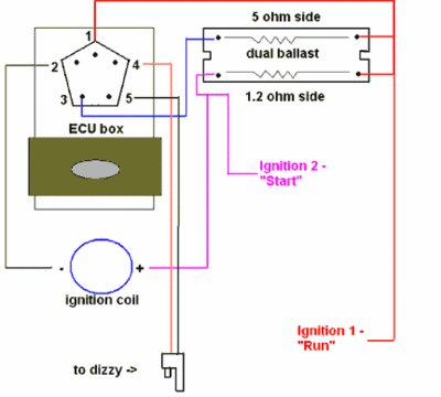
1/Remove the wiring connector from the orange box amplifier. This is a view of the rubber connector when removed and looking at the bottom.

2/Turn the ignition switch ON.
You should have battery voltage (within 1 volt) between earth and pin 1 (blue/yellow wire). Also pin 2 (black/yellow).
3/Turn the ignition OFF.
Pins 4 & 5 connect to the pick-up coil in the distributor. Connect an Ohm meter accross these two pins. The resistance should be within 150-900 ohms (400-600 prefered). If is isn't detatch the dual connector at the distributor and check there. If the coil is still not within spec replace it. Connect one lead of your ohm meter to earth and the other to either coil pick-up connector. If you get any reading at all replace the pick-up coil.
Pin 3 in my diagram is not used but should be connected to earth. Check this.
SET THE RELUCTOR GAP
The reluctor gap should be set with a non-magnetic feeler guage. 10thou in early ignitions and 8thou in those made after 1977. Set the gap by holding a feeler guage that is 2thou smaller against a reluctor tooth and move the pick-up against it. Tighten the adjusting screw and you will find that the gap is now right when you try it.


