-

Eddie - Frequent Poster
- Posts: 6212
- Joined: 16 Oct 2006 21:26
- Location: Terre Haute, Ind.
I still need to pressure test the heads.(I should have done that first but I was too eager to take em apart  ), CC the chambers, CC the exhaust and intake ports. I bought a CC'ing Burette from the Sciencemall.com for 68.00 bucks complete kit with burette, stand, clamp, petcock, glass not plastic, 100ML, so I'll have to re-fill it during the intake port meausrement, no biggie, I wasnt paying 300.00 for the other tool suppliers for the 200ML!! After all thats done I'll put them on the 'HeartBreaker"(@28") and of course I'll post em on here 1st!

-

Eddie - Frequent Poster
- Posts: 6212
- Joined: 16 Oct 2006 21:26
- Location: Terre Haute, Ind.
-

patrick - Frequent Poster
- Posts: 1323
- Joined: 09 Jul 2007 0:56
- Location: Washington State, U.S.A.
Oh, I forgot to mention open pressures. The installed height averaged around 1.880 I deducted .600 and Compressed them in the Rimac to 1.280 the readings were HIGH=326 LOW=317 result the springs were within 5%. I am using other springs,retainers and locks. This is to let Ian and MoParMan1972 of the results. Be advised 440source claims the ret.locks,keepers NOT to be used above .515 even though the springs will allow .600 before coil bind which occurs at 1.110,,
-

Eddie - Frequent Poster
- Posts: 6212
- Joined: 16 Oct 2006 21:26
- Location: Terre Haute, Ind.
- Moparman1972
- Frequent Poster
- Posts: 538
- Joined: 29 Apr 2006 17:10
- Location: Connecticut
thanks eddie i did see there claim & went for a comp cam 507 int 510 exst just to be safe i probably should pull the heads down & improve them (i know i should) but ive blown enough dough just doing what ive done so theyll have to do for now , ill use them as i bought them & in the meantime ill keep teaching myself stuff on cheaper locally available before i make any serious mods to parts i need to import ( the freight is a killer) once ive got it done & on the road ill be able to relax & take advantage of what ive learnt from this board & other sources this is all great info it keeps the brain ticking over thanks eddie
cheers ian
cheers ian
-

ianandjess - Frequent Poster
- Posts: 687
- Joined: 10 Dec 2005 12:18
- Location: australia
-

dave-r - Grumpy Old Man
- Posts: 9842
- Joined: 12 Oct 2003 21:45
- Location: North of the Tyne, England
Thanks Dave&Ian, I think there is enough spring for most apps up to .600 Lift. I bet you have much better quality retainers and Keepers than whats on it now Dave. These arent Chrome-Moly retainers or keepers, they're stamped steel, therefore they have the .500+ lift 'disclaimer, but with the cam you are runnning Ian it should still be fine to 6000 RPM's. Same as the factory stuff. 

-

Eddie - Frequent Poster
- Posts: 6212
- Joined: 16 Oct 2006 21:26
- Location: Terre Haute, Ind.
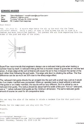
I had time to flow the #3 Intake/Exhaust port today. I couldnt use an entrance radius on the intake port because my instructor would not allow it. He was afraid the manometers would be contaminated if dirt or contaminates were flowed pass the screen into the meter vanes, so NO radius, it would have flowed much beter with it in place but here's what I came up with. At .100 the flow= 115CFM at .200=153CFM at.300=205CFM at .400=223CFM .500=235CFM .600=237 CFM the exhaust was very strong compared to the intake, of course I didnt use a pipe, just the exit of the port. .100=84 .200=133 .300=168 .400=190 .500=198 .600=206
-

Eddie - Frequent Poster
- Posts: 6212
- Joined: 16 Oct 2006 21:26
- Location: Terre Haute, Ind.
Also, the round clear plastic orfice is all the adaptors we have, it's 'bore' size is 4.25 so the bore is definitely shrouded and this also may affect the flow, maybe MoparMan1972 would know? I aksed the instructor if this would affect the flow and he said it sjouldnt that much but I suspect he is misinformed. He isnt that knowledgeable about performance. He;s a dealership technician, as are all of the instructors. The area of maximum performance and just 'fixing' things are completely different. I am learning a lot and plan to make subtle mods as well as finsihing flowing all the inatke/exhaust ports to establish a baseline on which to make further mods. The first thing I am going to do is backcut the intakes, then flow it to see if I picked up any additional flow. I mean to backcut ever so slightly, just placing a radius on the valve head, or 'ski jump' as the grinders/cutters refer it to. An interesting thing is I had to flow these smallblock Ford,(Aussie made Pro-Comps)  heads along with mine. The intake ports were the same almost with 210 CC intake ports mine at 212 and his valve was a smaller 2.08 compared to my 2.14 and the ports flowed virtually the same CFM. I would have thought they would have flowed worse through the smaller valve. This made me believe the port shape and valve seat were key in the flow numbers along with the reduced bore size.
 heads along with mine. The intake ports were the same almost with 210 CC intake ports mine at 212 and his valve was a smaller 2.08 compared to my 2.14 and the ports flowed virtually the same CFM. I would have thought they would have flowed worse through the smaller valve. This made me believe the port shape and valve seat were key in the flow numbers along with the reduced bore size.
Last edited by Eddie on 29 Jan 2009 18:24, edited 2 times in total.
-

Eddie - Frequent Poster
- Posts: 6212
- Joined: 16 Oct 2006 21:26
- Location: Terre Haute, Ind.
-

Eddie - Frequent Poster
- Posts: 6212
- Joined: 16 Oct 2006 21:26
- Location: Terre Haute, Ind.
-

Eddie - Frequent Poster
- Posts: 6212
- Joined: 16 Oct 2006 21:26
- Location: Terre Haute, Ind.
Sorry no readout graph from the computer. As soon as they figure out how to use it and teach me I'll post the Official results but this should whet your appetite. Also, I really dont care about the numbers, I want to establish the baseline and futire mods to progress forward in flow insteadof going backwards. I am very excited that they let me even use this flowbench. Now that I have a 'semi-handle' on things they are going to have to pry me off this thing!!! I even snuck the operators manual home with me, and the software Discs, I want to learn everything about this machine!! 

-

Eddie - Frequent Poster
- Posts: 6212
- Joined: 16 Oct 2006 21:26
- Location: Terre Haute, Ind.
I forgot to put a sparkplug in at first and had to start over! 
 I also used a standard 440 gasket,(4.340 fel-Pro blue for the seal to the adptor plate to the bottom of the head, I checked the seal leakage rates and it was at 0%

-

Eddie - Frequent Poster
- Posts: 6212
- Joined: 16 Oct 2006 21:26
- Location: Terre Haute, Ind.
airfuelEddie wrote:I aksed the instructor if this would affect the flow and he said it shouldnt that much.
I think it won't matter much too.
If you were measuring air flow through this tube, going from 4.25 to 4.38 would be a 6.2% increase in section, and so a 6.2% increase in flow at any given vacuum.
But what you're measuring is air flow through each valve and the port which precedes (or follows) it. The shape and size of the simulated combustion chamber is not too relevant, as long as the pump can create enough vacuum or pressure to take the maximum measurement.
I think the length of the tube would have a much bigger influence over the results than having a tube with a 4.38 bore.
-

fbernard - Frequent Poster
- Posts: 733
- Joined: 19 Oct 2003 20:41
- Location: Paris, France
Thank You Fabien! I am always impressed by your knowledge!fbernard wrote:airfuelEddie wrote:I aksed the instructor if this would affect the flow and he said it shouldnt that much.
I think it won't matter much too.
If you were measuring air flow through this tube, going from 4.25 to 4.38 would be a 6.2% increase in section, and so a 6.2% increase in flow at any given vacuum.
But what you're measuring is air flow through each valve and the port which precedes (or follows) it. The shape and size of the simulated combustion chamber is not too relevant, as long as the pump can create enough vacuum or pressure to take the maximum measurement.
I think the length of the tube would have a much bigger influence over the results than having a tube with a 4.38 bore.
 BTW, Fabien, I have a packet in the manual I brought home. It contains 2 pitot tubes to measure airflow stagnation and velocity. It also has a chart with density/temperature . I am reading and it seems very important to port development! I can find the airflow stagnation points in the port. I have to say, this flowbench can suck up to 1000 CFM's and it will literally pull your hand in the orfice! I had the airflow calibration set to 300 CFM when I tested that Intake/Exhaust port. You can put the airflow setting as close to what you think the port will flow maximum. This way the readings are more accurate because the parameters are within it's range of measurement. At least thats what the 'directions' said,
-

Eddie - Frequent Poster
- Posts: 6212
- Joined: 16 Oct 2006 21:26
- Location: Terre Haute, Ind.
Also if there was something I could use that attached to the port with enough adhesion as to not get sucked into the port opening, the instructor was nervous when I attached some silly putty to it but I took it off because he thought it would get sucked into the manometers, which are screened,(calibrated for the screen obstruction to airflow), and mess things up. Any ideas? It's gotta be pliable enough to shape into a radius, test, then remove without damaging the head or soft alloy.
-

Eddie - Frequent Poster
- Posts: 6212
- Joined: 16 Oct 2006 21:26
- Location: Terre Haute, Ind.
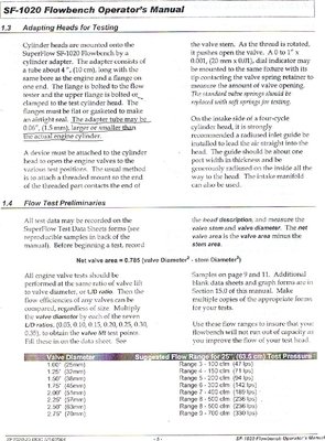
I just read this in the manual Fabien. I think the school needs to get a much larger adaptor plate.  It's standard 4",(4 inch hole into a 4.030) tube, then the gasket which is a standard fel pro blue 440 gasket at 4.340, then the head. It needs to be much much larger! Thats why the intake side was so weak I assume. The bench sucks through the intake port but blows through the exhaust port. You have to switch the settings when testing. I also had the stting on 300 when it should have been 400! Oh well, I am learning and having a blast!!

-

Eddie - Frequent Poster
- Posts: 6212
- Joined: 16 Oct 2006 21:26
- Location: Terre Haute, Ind.
-

Eddie - Frequent Poster
- Posts: 6212
- Joined: 16 Oct 2006 21:26
- Location: Terre Haute, Ind.
I asked him about that Ian and he suggested modeling clay. All I had at the time was silly putty, kids crap. It crumbles to easy. I'm gonna pick some up today at wally world. You have to have somethng that mimics the walls, roof ect exactly, only something thats pliable yet sticks to the sides all the while conforming to the shape of which each port has minute differences so a tooling plate will only be a burden. Plus when I start 'hogging' out those ports I'll need to expand it all the way around the circumference of the shape. I'll keep you posted on what I find out and the results after I get this figured out. BTW, what is perspex?ianandjess wrote:add 30% to those figures you got & theyre not as bad as you thought
can you shape a piece of perspex to give the desired effect 1 of the aticles i read recently sugested doing it that way
cheers ian
-

Eddie - Frequent Poster
- Posts: 6212
- Joined: 16 Oct 2006 21:26
- Location: Terre Haute, Ind.
When the machine was running I took a small ink pen and probed the walls and roof, floor, ect,, even small obstructions produced results that are eye opening, dramatically changing the flow! It shows just how 'sensitive' airflow really is. It also shows how much momentum and how heavy air really is. This guys sells a kit for 1k www.flowperformance.com
-

Eddie - Frequent Poster
- Posts: 6212
- Joined: 16 Oct 2006 21:26
- Location: Terre Haute, Ind.
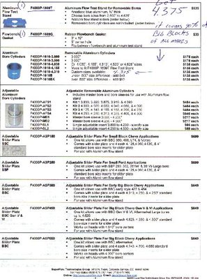
I once again called Steve Brezinski at SuperFlow and he sent me this parts list for the adaptor plate and cylinder spacer tube plus gasket. It comes to 731.00!! I sure hope the school will approve it's purchase. I also called some acrylic suppliers for the option of buying it myself and cutting it to fit my application. At this point, I am on a buying freeze. I cant buy any more parts or tools, instead saving for a special project of which I have comitted myself to financially. 
-

Eddie - Frequent Poster
- Posts: 6212
- Joined: 16 Oct 2006 21:26
- Location: Terre Haute, Ind.
